MSPM0
Setting
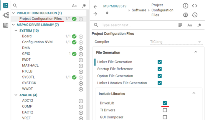
STEP 1 : SysConfig - Configuration NVM
easyDSP uses the code generated by SysConfig. The following guide describes the configuration process for SysConfig, based on version 1.25.0.
At first, you can set the 'Configuration NVM' item such as BCR and BSL configuration.
If you wish to use the factory default values, you can skip STEP 1. Otherwise, please refer to the following.
First, configure the BCR section. 'Enable Fast Boot Mode' should be disabled, and 'Enable BSL' should be enabled.
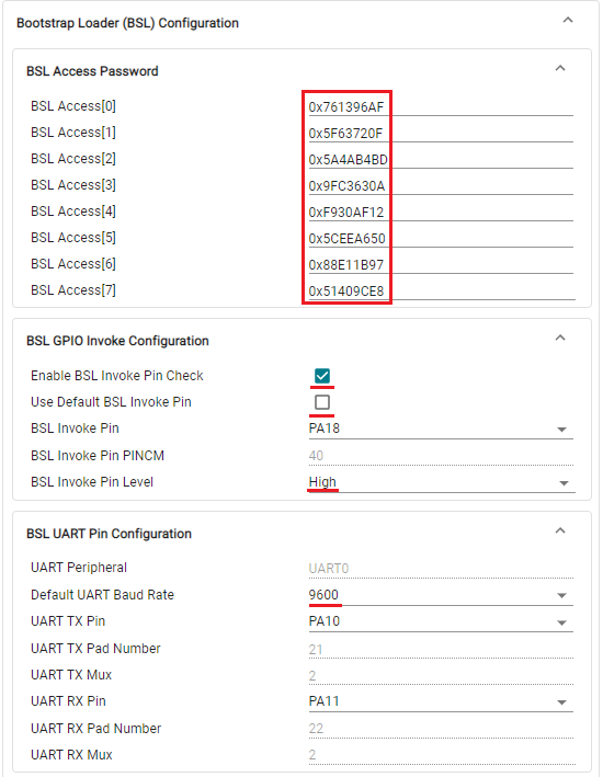
Next is the BSL Configuration section.
Set the 32-byte BSL password required to enter the BSL.
Depending on the MCU type, either input the password directly or as a SHA256 hashed value.
If using the default value from SysConfig, the BSL password will be 32 bytes of all 0xFF.
Enable the BSL Invoke Pin Check.
You can use the default BSL Invoke Pin or set a custom one if needed. In this case, the BSL Invoke Pin Level must always be set to High.
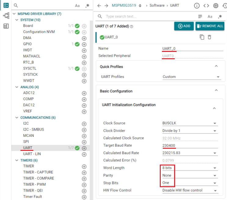
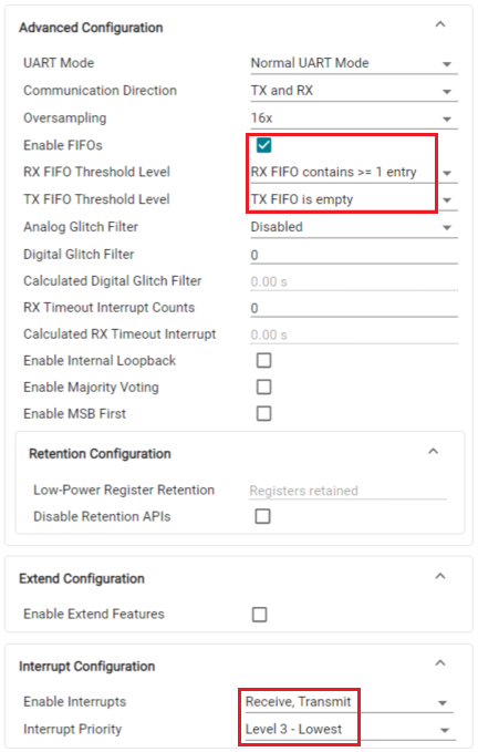
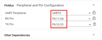
You can set the BSL UART Pin. Some MCUs allow configuring the Baud Rate, which should be set to 9600 in that case.
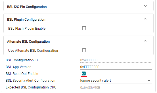
Finally, enable or disable BSL Read Out Enable. If enabled, the flash data is read to perform a flash Verify operation. If disabled, the flash CRC is read to perform the Verify operation.
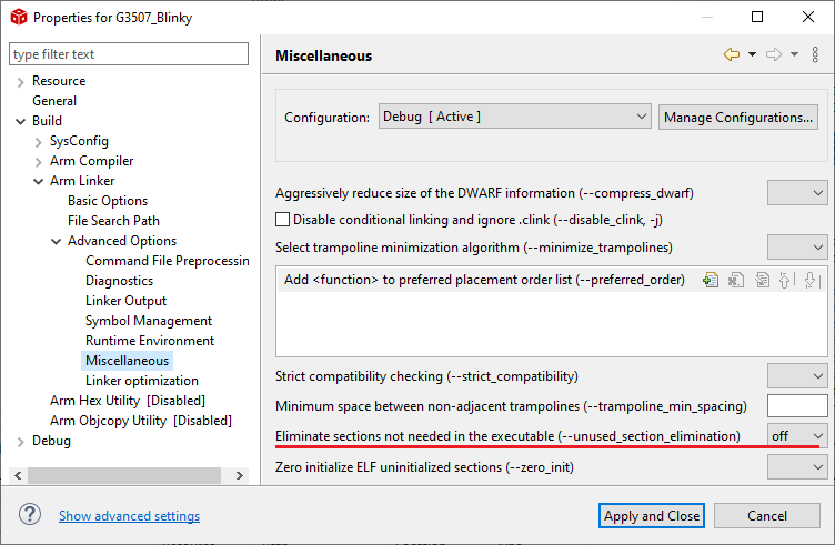
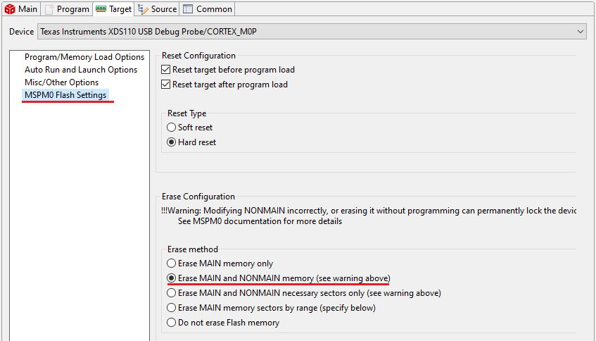
Please note: There is a precaution. The flash memory in the NONMAIN area cannot be programmed using easyDSP. Therefore, any initial settings or subsequent changes made in this step must be programmed to the flash using a debugger or another tool.
STEP 2 : Hardware
As confitured in STEP 1 or by TI factory default, connect BSL_invoke, BSLRX and BSLTX to easyDSP header.
If you use TI factory default (No change to NONMAIN flash in STEP 1), refer to the target MCU datasheet to identify pin number of those pins. For instance, BSLRX, BSLTX and BSL_invoke has pin number 26, 27 and 22 respectively for MSPM0L1306xRHB. For instance, BSLRX, BSLTX and BSL_invoke has pin number 57, 56 and 11 respectively for MSPM0G3507SPM.
Note that BSL_RX and BSL_TX belong to UART0.
![]()
Other considerations :
- Direct connection between easyDSP /RESET and MCU NRST.
- RX and TX pins of easyDSP header are pulled up with 100kOhm resistor in the pod.
- In case pull-up resistor is attached, resistor value should be higher than several k Ohm.
STEP 3 : SysConfig - Others
Since easyDSP uses the DriverLib library for UART communication, you must include it in your project.
![]()
.
Since the NRST pin must be used in NRST mode, do not check 'Disable NRST Pin'
![]()
Next, we have the UART configuration.
Since the BSL_RX and BSL_TX pins are always UART0, create a UART0 channel with the name UART_0.
Select the communication baud rate for variable monitoring. The selected value must be the same as the baud rate selected in the easyDSP project.
The UART communication protocol is 8 bits, no parity, and one stop bit.
![]()
Enable the FIFO, and set the FIFO Threshold Level as below picture.
Activate both the Receive and Transmit interrupts, and set their priority to the lowest level.
First, the target pins are determined in 'PinMux', and various settings are performed in 'Pin Configuration'.
In the following figure, based on the factory release of MSPM0G3519SPZR, BSLRX is assigned to pin 34 and BSLTX is assigned to pin 33.
The pull-up resistors for the TX/RX pins are activated, and the 'Drive Strength Control' for the TX pin is set to High if possible.
STEP 4 : easyDSP source file
Please include driverlib from TI in your project since easyDSP uses it for UART communication.
Two files are provided for easyDSP communication (easyMSPM0.h, easyMSPM0.c). Please include them in your project. You can find them in the easyDSP installation folder (\source\MSPM0).
Please include easyMSPM0.h in the main.c. And in the main(), call easyDSP_init() after the initialization of MCU.
In the easyDSP_init() function, all the setting for easyDSP monitoring are done.![]()
STEP 5 : IDE
1. Hex file (Intel format) is used for flash programming. So it should be created in every compiling time in the same folder of output file (ex *.out) with same file name. The hex file extension could be either 'hex' or 'ihex'. easyDSP first check if the hex file with extension 'hex' exists and use it for flash programming. If the hex file with extension 'hex' doesn't exist, easyDSP uses the hex file with extension 'ihex'. Pleae set your IDE accordingly to create hex file in every compiling time.
Please refer to the setting of CCS. Especially for CCS, memory width should be 8.
2. For easyDSP monitoring, the debug information should be included in the output file (ex, *.out). And the option of assembler, compiler and linker should be set accordingly.
3. Depending on compiler's optimization level and linker setting, the unused variables could be excluded from the debug information and not shown in the easyDSP.
If you like to avoid this, don't use compiler optimization and set the linker option properly. Like below in case of CCS.
4. In case of CCS, to program NONMAIN memory area of flash, below option should be set.