TM4C setting
STEP 1 : Hardware
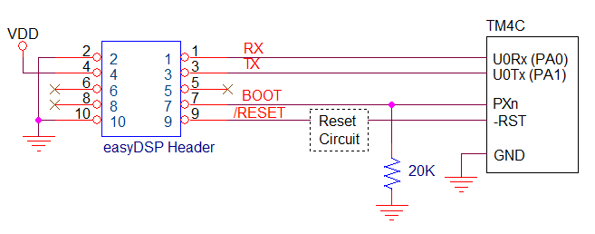
easyDSP uses MCU's ROM boot loader to access the flash memory. So the
UART0 channel (PA0/PA1) that is used in the ROM boot loader should be used for easyDSP.
Otherwise, easyDSP can support only
monitoring, not flash programming. Also the source file easyTM4C.c should be
modified accordingly by you.
PXn pin acts as a boot pin and you can select
it in the easyTM4C.h file. But caution should be taken when selecting boot pin
:
1. PC0-3, PD7 and PE7 can't be used for TM4C129x
MCU
2. PC0-3, PD7 and PF7 can't be used for TM4C123x
MCU
3. In case other circuitry is connected to this pin than easyDSP BOOT pin, this circuit
should not issue the
output signal until ~1sec after MUC reset release.

Other considerations :
- In case there is a reset IC between easyDSP /RESET
and MCU -RST, it should transfer easyDSP /RESET signal to MCU -RST within
0.5sec.
- TX and RX pin of easyDSP header is pulled up with 100k Ohm
resistor inside of easyDSP pod.
- You can use the boot pin (PXn) for other purpose in your
program
STEP 2 : Modification of easyDSP header file
Two files are provided for easyDSP communication
(easyTM4C.h and easyTM4C.c). Please include them in your project. You can
find them in the easyDSP installation folder (\source\TM4C).
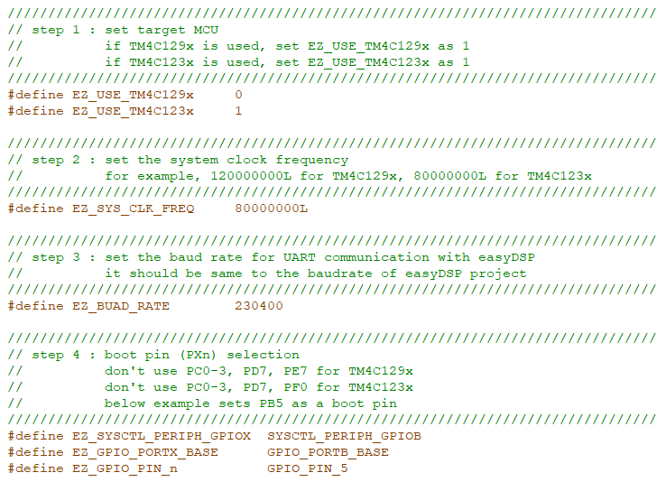
In
the file, please set a target MCU, MCU clock,
baudrate of easyDSP communication and boot
pin.
The baud rate should be same to that of easyDSP
project.

STEP 3 : Calling easyDSP functions
Please include
easyTM4C.h in the main.c. And in the
main(), call
easyDSP_boot() very begining and
call easyDSP_init()
after the initialization
of MCU.
In the easyDSP_boot()
function, it is decided which code will be executed, either user program in the flash or ROM boot loader, depending on the status
of boot pin. In case you don't use flash programming by
easyDSP, no need for this function.
In the easyDSP_init() function, all necessary
setting for easyDSP monitoring are done.

STEP 4
: IDE
setting
1. Hex file (Intel format) is used
for flash programming. So it should be created in every compiling time in
the same folder of output file (ex *.out) with same file name. The hex
file extension could be either 'hex' or 'ihex'. easyDSP first check if the hex
file with extension 'hex'
exists and use it for flash programming. If the hex file with
extension 'hex' doesn't exist, easyDSP uses the hex file with extension 'ihex'. Pleae set your
IDE accordingly to create hex file in every compiling
time.
Please refer to the setting
of CCS. Especially for CCS, memory width should be 8.


2.
For easyDSP monitoring, the debug information
should be included in the output file (ex, *.out). And the option of
assembler, compiler and linker should be set accordingly.
3. The unused variables
could be excluded from the debug information depending on compiler's
optimization level and linker setting. If necessary, you can set the linker
option so that the unused variables are not
excluded.
4. To compile inline functions in the
easyTM4C.c, plase enables c99 mode in the compiler options if
necessay.
STEP 5
: Other
setting
1. To allow
easyDSP to access the flash, the protection feature of flash should be
disabled so that the flash may be written, erased, executed or
read.
2. EN bit of BOOTCFG register of MCU should be 1. With this, the
booting mechanism is decided by easyDSP_boot() function.
3. easyDSP can perform flash programming only when either all
the flash is empty or easyDSP source file is programmed in the
flash.
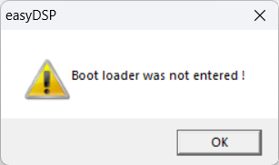
For the other situation than above, you
will face the error message below and you
should use debugger to program flash.


