UCD3138 Setting
easyDSP connection
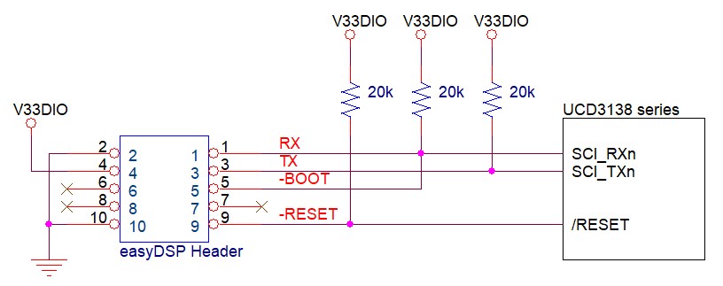
easyDSP preparationPlease select the UART channel and pins according to your board setting. No constraints to selectable channel and pin.
Then connect them to easyDSP like below.
In case you don't use easyDSP provided bootloader for flash programming, no need to connect -BOOT and -RESET pins.
Other considerations :
- When reset, easyDSP -RESET pin goes low for about 500msec.
- In case there is a reset IC between easyDSP -RESET and MCU /RESET, easyDSP -RESET signal should be transferred to MCU within 0.5sec.
- RX and TX pins of easyDSP header are pulled up with 100kOhm resistor in the pod.
Three files are provided for easyDSP communication and flash programming (easyUCD.h, easyUCD_comm.c and easyUCD_boot.c). Please include them in your project. You can find them in the easyDSP installation folder (\source\UCD).
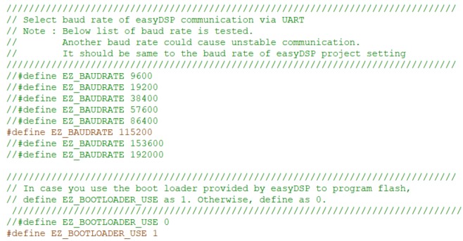
Please set the conditions of easyUCD.h. Below example shows you use UCD3138, UART0 with RX pin# 23 and TX pin# 22 at the baudrate 115200 and easyDSP provided bootloader for flash programming. Note that the baudrate shoud be same to one in the easyDSP project setting.
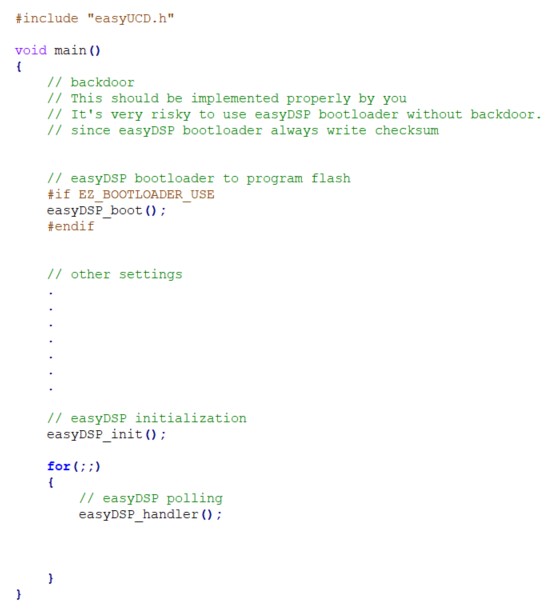
Then please include easyUCD.h in the file main.c. In the very beginning of main(), you have to implement a backdoor. It is mandatory for UCD3138 series especially with easyDSP. Please check TI's manual on how to implement the backdoor. Right after the backdoor, please call easyDSP_boot() in case you uses easyDSP provided bootloader for flash programming. Then call easyDSP_init() after some initialization codes. Last but not least, call easyDSP_handler() in the infinite loop. If there are many tasks in the infinte loop, call easyDSP_handler() multiple times so that easyDSP can secure time slot for its communication to MCU.

easyDSP provided bootloader
There are various methods provided by the manufacturer for flash programming, such as JTAG debugger and PMBUS-based development environment.
Additionally, easyDSP provides a bootloader that uses the UART communication channel to easily perform frequent program modifications during firmware development.
However, this method has several limitations and precautions, so please carefully consider whether to use it.
If you do not use the easyDSP provided bootloader (i.e. set #define EZ_BOOTLOADER_USE 0 in easyUCD.h), please skip this chapter.Limitations and Precautions:
1. The bootloader easyDSP provides is the function (name : easyDSP_boot) and it resides in the user program. Therefore it can program flash only when it is already programmed in the flash. In case flash is empty or flash doesn't have easyDSP bootloader, you can't enter into the bootloader. In this case, you have to use the debugger (/w PMBUS or Jtag) to program flash including checksum. And in same principle, at the very beginning, at least once, you have to use debugger to program flash and checksum.
2. The bootloader could not work if some malfunction happens during flash programming operation. For example, there is no bootloader available if programming flash fails after erasing flash. In this case, you should use debugger to program flash.
3. Backdoor should be implemented to avoid program flash lockup even in case of easyDSP bootloader malfunction.
4. easyDSP_boot() calls software interrupt #10 to enter supervisor mode. So, this #10 function should be implemented in the software_interrupt.c. This is the default setup of all TI provided example project. But please keep it mind that your project should do same.
5. When accessing flash, the functions and variables used are located in RAM, which consumes a certain amount of RAM capacity.
Preparation for Use:
1. As mentioned earlier, declare EZ_BOOTLOADER_USE as 1 in easyUCD.h, include the easyUCD_boot.c file in your project, and call the easyDSP_boot function in the main function.
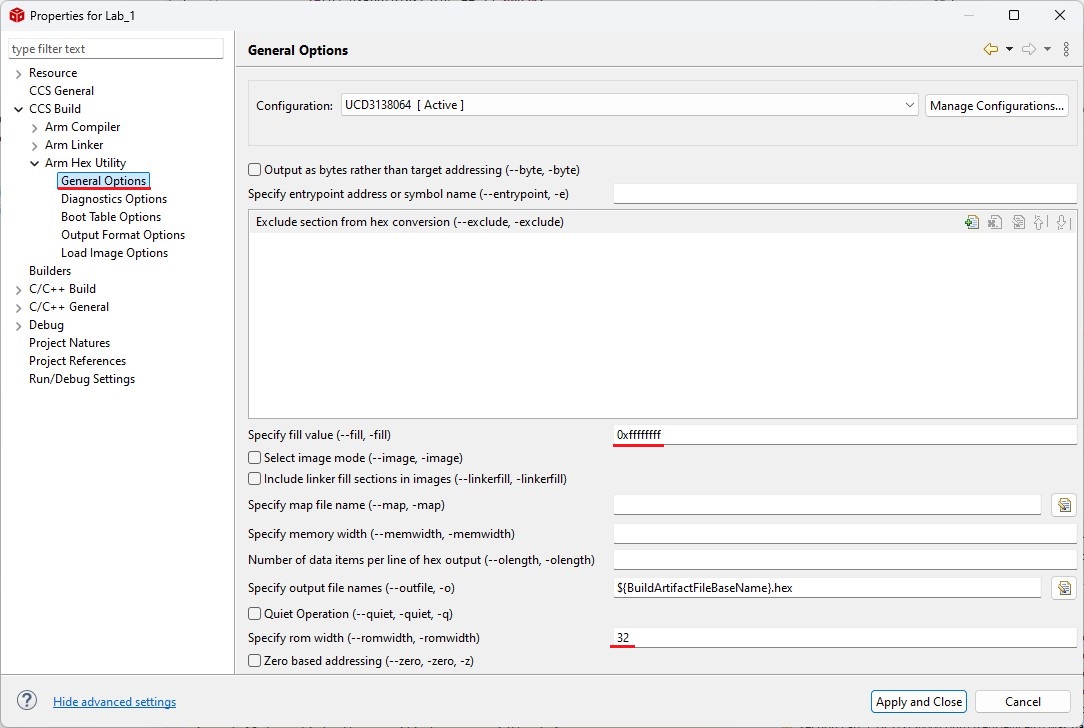
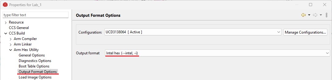
2. Set up your IDE to generate an Intel-format hex file with the same name as the output file in the same folder after each compilation. The hex file is used for flash programming. For example, in CCS, refer to the following settings: set the fill value to 0xFFFFFFFF, ROM width to 32, and Intel hex format.
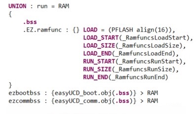
3. To program and erase a flash, this bootloader should reside in RAM area. So, to copy the bootloader code in flash to RAM, and to minimize the additional RAM size for this, some modification should be done in a linker command file. Please check below : To minimize the required RAM size, by using UNION, .bss and .EZ.ramfunc region are overlapped in RAM. In addtion, .bss section of two files are separately allocated to RAM.
How to use :
Refer to here for how to use flash dialog.
qnote
The TI provided example project uses 'qnote' structure variable to implement quick floating value calculation. easyDSP treats the qnote structure variable as float type ranging from 0.00001 to 999999. You can read and write qnote structure variable as it is float type when it is not an array.
IDE setting
1. legacy COFF as an output format.
2. UCD3138 series supports only big Endian. Please set the 'Device endianess' as 'big'.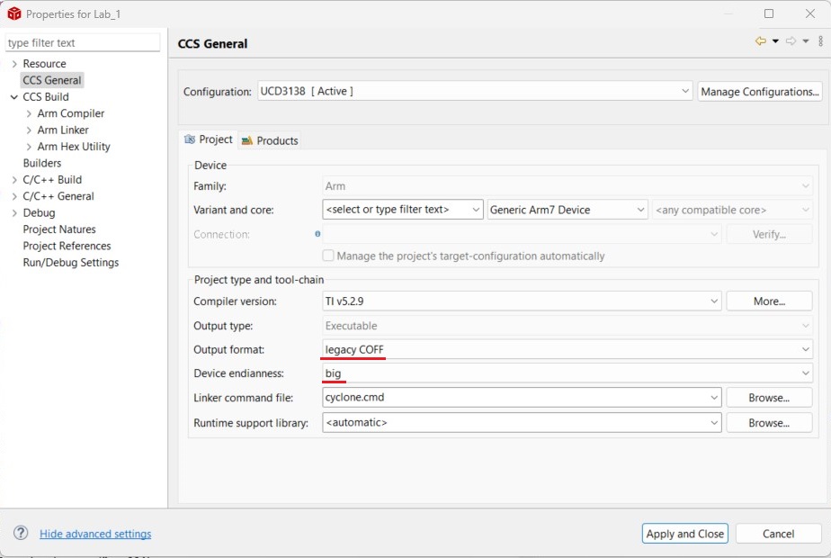
3. For easyDSP monitoring, the debug information should be included in the output file (ex, *.out). And the option of assembler, compiler and linker should be set accordingly.
'MCU > Load Symbol'
menu 
If you are not using the easyDSP bootloader, you must run this menu to update the reprogrammed variable information every time the MCU flash is programmed again with a debugger or similar tool.
If you are using the easyDSP bootloader, you do not need to use this menu. Instead, when you program the flash, you can simply select "Yes" in the message box that asks whether to retrieve the variable information from the updated user program.